

How to Build a Flexible Automation Cell with a Delta Pick and Place Robot
Core Hardware Architecture of a Flexible Cell
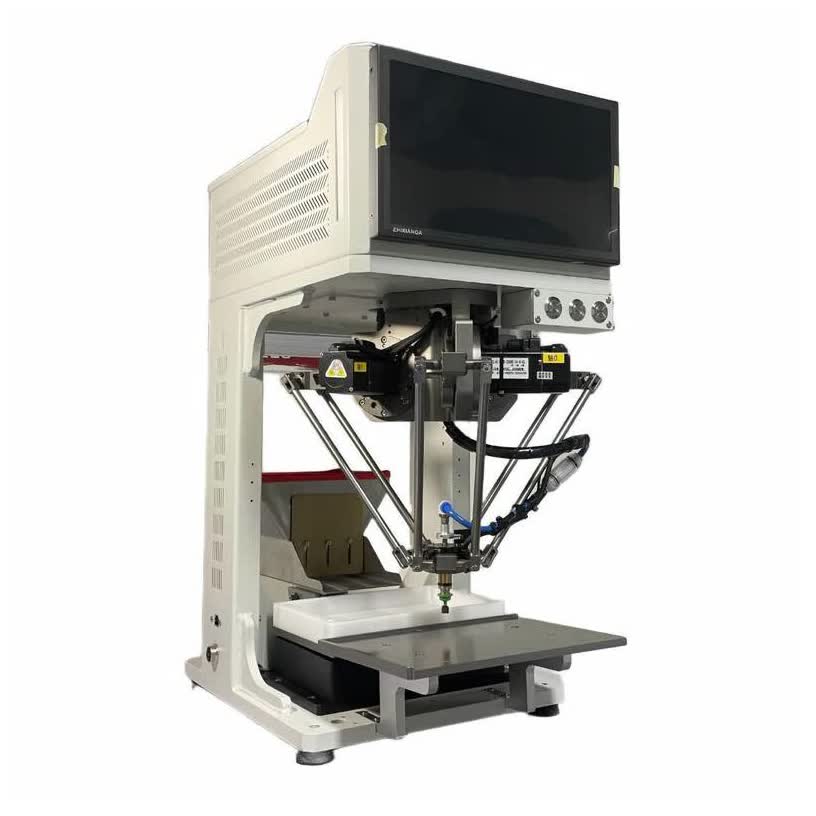
A robust flexible automation cell consists of four tightly synchronized functional blocks: the overhead kinematic manipulator, the parts feeding module, the optical vision system, and the central programmable controller. The physical foundation of the workstation is a heavy welded steel or extruded aluminum profile frame designed to resist harmonic oscillations. Because parallel robots generate substantial dynamic accelerations reaching 10g during high-speed pick cycles, the base frame must provide high torsional rigidity to isolate mechanical vibrations from sensitive optical sensors.
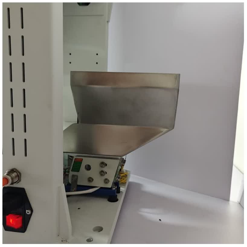
The feeder subsystem sits directly beneath the robot kinematic envelope, typically combining a bulk storage hopper with a multi-axis vibration platform. Optical cameras mount on overhead crossbeams to capture illuminated parts, while lower inspection optics mount beneath the tooling path to verify component orientation in flight. A programmable logic controller or industrial PC coordinates motion profiles, feeder pulse sequences, and sensor feedback. Integrated emergency stop circuits, pneumatic pressure monitoring switches, and safety interlocks ensure safe human-machine interaction during production shifts.
Feed System Integration and Part Presentation
Reliable component presentation is the primary prerequisite for continuous pick-and-place operation. Traditional vibrating bowl feeders rely on customized mechanical tracks that orient parts through passive geometric filtering, making them prone to jamming on thin or asymmetrical components. A flexible feeder utilizes multi-axis electrodynamic or voice-coil actuators to agitate components on a flat pick plate. By modulating frequency, amplitude, and directional phases across three dimensions, the feeder flips inverted parts and disperses tangled clusters evenly across the surface.
The feeding sequence operates under closed-loop optical supervision: - A bulk hopper dispenses raw components onto the feeder tray based on optical surface density measurements. - The flexible platform executes brief directional vibrations to spread parts across the illuminated field of view. - Backlighting illuminates parts from beneath the translucent plate, creating high-contrast silhouettes for optical inspection. - The robot picks all correctly oriented components identified by the vision system. - An intelligent recycling cycle gathers rejected or unpicked components via edge drop chutes or reversible conveyor sweeps.
Vision Guidance and Tracking Alignment
Optical vision guidance provides the spatial intelligence required to coordinate robotic motion with dynamic part feeding. The vision architecture typically employs a dual-camera layout. An upper global camera, featuring five to twelve megapixels resolution, mounts above the feeder plate to detect part presence, center coordinates, and rotational planar orientation. When the feeder pauses its vibration cycle, the camera triggers synchronized illumination to capture sharp part contours without motion blur.
A secondary lower camera mounts beneath the robot operational travel path to perform high-speed in-flight inspection. Once the end-effector retrieves a component, the Delta Pick and Place Robot transfers the part across the lower camera field of view. The optical processor inspects critical pin straightness, surface defects, and polar alignment within milliseconds. This in-flight verification eliminates secondary mechanical centering nests, allowing the system to maintain continuous cycle rates of 3,000 to 4,500 parts per hour while achieving placement accuracy tolerances of ±0.05 mm.
Kinematic Envelope and Layout Optimization
Optimizing the physical layout of a flexible cell requires careful alignment between robot reach, feeder dimensions, and output conveyors. Workstation platforms such as the FDR-M200 utilize an overhead parallel manipulator with a working radius of R200 mm to R400 mm and a vertical stroke capability of up to 400 mm. The inverted dome workspace creates a concentrated operating zone that covers the feeder pickup plate, the in-flight camera, and the destination packaging nest within minimal travel spans.
Key spatial considerations for layout optimization include: - Positioning the flexible feeder pick window within the center of the robot working envelope to maximize kinematic acceleration. - Keeping vertical travel strokes under 50 millimeters to compress cycle times to fractions of a second. - Mounting electrical control enclosures and pneumatic manifolds directly beneath the workstation table to minimize external floor footprints. - Installing quick-release reject bins directly adjacent to the placement nest to discard defective components without leaving the primary motion corridor.
By arranging hardware in a concentric layout, system designers achieve compact benchtop footprints that drop directly into existing manual production lines.
Cell Communication and Control Protocols
Seamless real-time communication between the robot controller, vision computer, and feeder driver prevents operational bottlenecks. High-speed industrial fieldbuses, such as EtherCAT, PROFINET, or dedicated Ethernet TCP/IP sockets, link the control elements. When the vision processor completes contour analysis, it packages component X-Y coordinates, angular orientation values, and pick-readiness flags into a structured data packet.
Automation manufacturers like FIDER standardize coordinate exchange protocols to ensure reliable handshake sequencing: - The vision controller transmits target coordinates to a FIFO buffer within the robot motion controller. - Handshake signals trigger feeder vibration stops during camera exposure to prevent optical blurring. - Hardware encoder tracking synchronizes the robot end-effector with moving downstream conveyor belts for uninterrupted placement. - RS232 and digital input-output lines regulate bulk hopper replenishment based on feeder load cell thresholds.
This deterministic network structure prevents communication latency from degrading motion performance, ensuring continuous synchronization across all automation subsystems.
Commissioning and Changeover Protocols
The definitive operational advantage of a flexible cell is rapid batch changeover. Transitioning between different component geometries requires no mechanical disassembly or re-machining of guide tracks. Operators load a pre-configured software recipe from the graphical human-machine interface, adjusting vibration frequencies, optical inspection thresholds, and vacuum pick coordinates within minutes.
Standard commissioning and changeover protocols follow a systematic procedure: - Purging remaining components from the feeder surface into collection bins using automated forward vibration sweeps. - Loading the new part vision template and setting contour tolerance limits for quality inspection. - Adjusting vacuum gripper suction cup sizes or magnetic tooling if component physical properties require different end-effectors. - Running a test cycle of twenty parts to verify pick repeatability and coordinate calibration before initiating full-speed production.
Deploying a flexible Delta Pick and Place Robot workstation provides modern manufacturers with the agility required to handle high-mix small-part assembly while maintaining high-volume production throughput. To discuss flexible feeding workstation configurations or evaluate component handling requirements, explore detailed system specifications at https://www.fdrautomation.com/ to schedule an engineering consultation.
FIDER
FIDER
Legal Disclaimer:
EIN Presswire provides this news content "as is" without warranty of any kind. We do not accept any responsibility or liability for the accuracy, content, images, videos, licenses, completeness, legality, or reliability of the information contained in this article. If you have any complaints or copyright issues related to this article, kindly contact the author above.
